Working time calculation of ultracapacitor
The super capacitors are divided into two layer capacitors and pseudo capacitors. It has the characteristics of high power density, short charging time, long service life, good temperature characteristics, energy saving and environmental protection.
Supercapacitors can be quickly charged and discharged. Peak currents are limited by their internal resistance, and even short circuits are not fatal. The resistance of a supercapacitor prevents it from discharging rapidly. The time constant of a supercapacitor is 1-2 s. It takes about 5_to discharge completely in a resistor-capacitor circuit, which means that if a short circuit is discharged, it takes about 5-10 s (because of the special structure of the electrode, it actually takes several hours to completely release the remaining charge).
For trickle charging RTC
Typical RTC Trickle Charger internal circuit
The calculator determines the working time of the supercapacitor when it is powered by the supercapacitor according to the starting and ending voltages, discharge currents and capacities of the capacitor.
Among them:
- The maximum Vcap corresponds to the maximum value of the VCC, and the relevant data can be consulted, i.e. (VCC maximum) - diode voltage drop.
- The minimum Vcap is the minimum value of the working voltage of the RTC oscillator, and the relevant data can be consulted.
- The maximum value of IBAT is the maximum current of the battery, and the relevant data can be consulted.
- The typical IBAT value is the typical battery current defined at 25 C and nominal power supply voltage, and the relevant data can be consulted.
- The maximum value of VBAT is the maximum voltage of VBAT pin, and the relevant data can be consulted.
When calculating the working time of linear IBAT, it is assumed that the oscillator current is proportional to the input voltage, that is, the resistance characteristic. The equivalent resistance of the circuit is calculated by the IBAT maximum and VBAT maximum provided in the data, which is used to calculate the battery backup time.
Specification table example
Recommended DC working conditions(TA= -40°C to +85°C)
| Parameter | Symbol | Condition | Min | Typical | Max | Potential |
| Supply voltage | VCC | 2.7 | 3.0 | 3.3 | V | |
| Battery voltage | VBAT | 1.3 | 3.0 | 3.7 | V | |
| Table 1 | ||||||
DC electrical characteristics(TA= -40°C to +85°C)
| Parameter | Symbol | Condition | Min | Typical | Max | Potential |
| Battery current | IBAT | 600 | 1000 | nA | ||
| Table 2 | ||||||
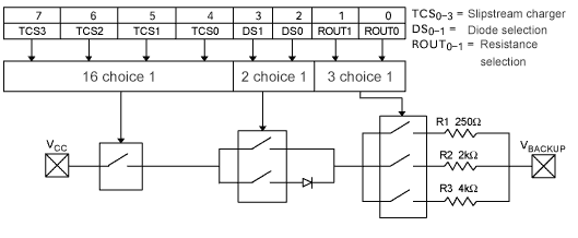
Figure 1
Note: Some diode selection circuits allow the selection of 1 or 2 diodes in series, while others allow the selection of 0 or 1 diodes. It is assumed that the voltage drop of each diode is 0.7V.
Typical RTC circuit with super capacitor backup power supply
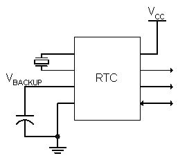
Figure 2